Inertia Tensor Calculation \(\def\dif{\text{d}}\)#
From the equation we developed in the preceding section for angular momentum, we can easily see that if we have unity angular rate in all three aircraft axes (\(P=Q=R=1\)), then any non-zero products of inertia (the off-diagonal terms) will result in angular momentum that is not aligned with the angular rate.
In other words - application of angular rate about axes for which the products of inertia are non-zero results in a net force, and requires net torque to maintain steady rotation.
Conceptually, this can be difficult to grasp - but is a consequence of the choice of aircraft body axes. Although we defined the aircraft body axes with centre at the centre of gravity, the orientation of the axes was arbitrarily chosen to be nose/wing/down.
For a general 3D body, it is always possible to find three mutually-orthogonal axes about which the products of inertia are zero. For simple bodies, these are obvious - see Figure which shows a simple cylinder with two rotation axes, both of which pass through the centre of mass.
It should be immediately obvious though, that free of any torque the cylinder could rotate indefinitely at a constant rate about one of these axes, but not about the other. Around the axis down the centre axis of the cylinder, the products of inertia would be zero. Around the other axis, they will be non-zero. This concept can be extended to our aircraft.
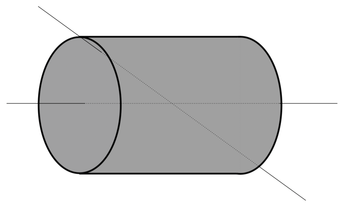
Fig. 55 Cylinder with two rotational axes shown.#
Finding the Principal Inertia Tensor#
We wish to find a set of axes such that the a new inertia tensor, \([\mathbf{I}]_p\) is diagonal and produces the same angular momentum when translated into the original co-ordinate system. That is if:
and these two axes systems can be related by a transformation matrix \(T\):
hence
this is known as a “similarity transformation”, and we will use Equation (34) to determine the orientation of our principal axes with respect to aircraft axes.
We assume that our transformation is a rotation in the pitch axes, and we call this angle \(\theta_p\) to denote ‘principal’. The transformation is then:
Since the total angular momentum is conserved, irrespective of what axes we pick, we can formulate this as:
or
where the Eigenvalues \(\lambda_i\) for \(i=1,2,3\) are the principal moments of inertia. Hence we need to solve the determinant of \(\left(\lambda_i-\mathbf{I}\right)\) to obtain \(I_x^p, I_y^p, I_z^p\).
hence the characteristic equation is a cubic in \(\lambda_i\):
thankfully, the symmetry of our aircraft often means that we can assume most products of inertia are zero (see previous section), and the result is a quadratic in \(\lambda_i\). This is best demonstrate with an example - we will calculate the moments of inertia, the products of inertia, and then calculate the principal moments of inertia the the orientation of the principal axes.
Moments and Products of Inertia Worked Example#
A biplane is modelled as four wings, an engine and a fuselage. The engine is represented as a point mass of 50kg, each wing as a 5m long uniform beam of mass per unit length equal to 3kg/m and the fuselage as a thin cylindrical shell 5m long, 1m outside diameter, 3mm thick and a density equal to 2720\(\frac{\text{kg}}{\text{m}^3}\). With respect to a frame of reference centred on the tails of the biplane each element is located as follows:
Component |
Position Vector/m |
|---|---|
Engine |
[5, 0, 1] |
Upper port wing root |
[3, 0, 2] |
Lower port wing root |
[3, 0, 0] |
Upper starboard wing root |
[3, 0, 2] |
Lower starboard wing root |
[3, 0, 0] |
Calculate the position of the centre of mass and the inertia matrix. Is the inertia matrix also the principal inertia matrix? If not calculate the principal moments of inertia, and their orientation.
Solution#
First, from the density and areas we can determine the location of point masses at the position vectors given above:
Element |
Density/dimension |
Dimension |
Mass |
Position |
|---|---|---|---|---|
Engine |
- |
- |
50kg |
[5, 0, 1] |
Upper port wing root |
3 |
5 |
15kg |
[3, 0, 2] |
Lower port wing root |
3 |
5 |
15kg |
[3, 0, 0] |
Upper starboard wing root |
3 |
5 |
15kg |
[3, 0, 2] |
Lower starboard wing root |
3 |
5 |
15kg |
[3, 0, 0] |
Fuselage |
2750 |
n/a |
? |
? |
We need to calculate the mass of the fuselage which is an empty cylinder. Can use two approaches for this:
and then the mass is simply \(m_{fus}=\rho\cdot V=127.8\text{kg}\). Alternatively we can determine the mass per unit length of the fuselage by integration in a circle, and then along the length \(m_{fus}=l\cdot\int^{2\pi}_0\int^{0.5}_{0.497}\rho r\dif r\dif\theta\). Both get the same answer.
The centre of mass is given by integrating the product of mass per unit length (\(mpl_{fus} = 127.8/5=25.56\)) and the length, and dividing by the total mass:
Which is fairly common sense, but this introduces you to the concept of determining the centre of mass which for this case is located at [2.5, 0, 0].
The total mass of the system is therefore:
now we may determine the location of the centre of mass. We know that since nothing has a non-zero y-ordinate, that the y-location of the centre of mass is zero. For \(x\) and \(y\) we must sum the products of the mass and the ordinates as follows:\
Element |
\(m_i\cdot x_i\) |
\(m_i\cdot z_i\) |
|---|---|---|
Engine |
250 |
50 |
UP Wing |
45 |
30 |
LP Wing |
45 |
0 |
US Wing |
45 |
30 |
LS Wing |
45 |
0 |
Fuselage |
319.5 |
0 |
Total |
749.5 |
110 |
So the centre of mass may be determined:
We can now determine the moments and products of inertia, noting that the ordinates are taken with respect to the centre of mass:
Element |
\(r_x\) |
\(r_z\) |
\(m_i\cdot x_i^2\) |
\(m_i\cdot z_i^2\) |
\(m_i\cdot x_i\cdot z_i\) |
|---|---|---|---|---|---|
Engine |
1.85 |
0.54 |
171.125 |
14.58 |
49.95 |
UP wing |
-0.15 |
1.54 |
0.3375 |
35.574 |
-3.465 |
LP wing |
-0.15 |
-0.46 |
0.3375 |
3.174 |
1.035 |
US wing |
-0.15 |
1.54 |
0.3375 |
35.574 |
-3.465 |
LS wing |
-0.15 |
-0.46 |
0.3375 |
3.174 |
1.035 |
Fuselage |
-0.65 |
-0.46 |
54 |
27 |
38.21 |
Total |
- |
- |
226.475 |
119.076 |
83.3 |
So the moments and products of inertia are:
Hence our inertia matrix is:
This has elements in the off-diagonal, so it is not the principal inertia matrix. We find the principal inertia matrix by solving a simplified determinant - we know that the principal moment of inertia around \(y\) is the same as the one we have calculated, so we may disregard the centre row and column, and calculate the determinant of the [2x2] matrix instead.
the two Eigenvalue solutions are the values for our principal moments of inertia in \(x\) and \(z\). Hence:
we use the similarity transform to determine the orientation of our principal axes:
we can take a single location and solve for theta - taking the first row and column location of both we get: